
Robot platforms & motion components / Senfar
Build the Robot.
Power the Motion.
Mobile Platforms. Servo Motors. Joint Actuators.
Engineered for Robotics Integration.
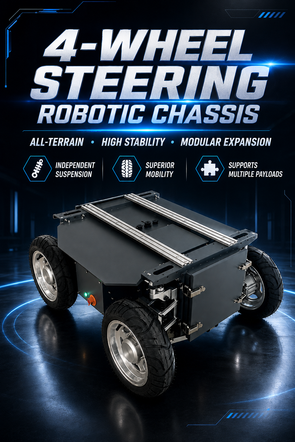
01 / Mobility foundations
Platforms and motion components shaped around the robot you are building.
Senfar supplies mobile robot chassis, education and research robots, hub servo motors, joint actuators, steering-drive modules, and motor drivers for global robotics programs.
From platform selection to integration planning, start with verified project requirements.
Explore the architecture02 / Product families
8 product families, one robotics integration path.
Explore representative robot platforms and the core motion components used to build, steer, and control them.
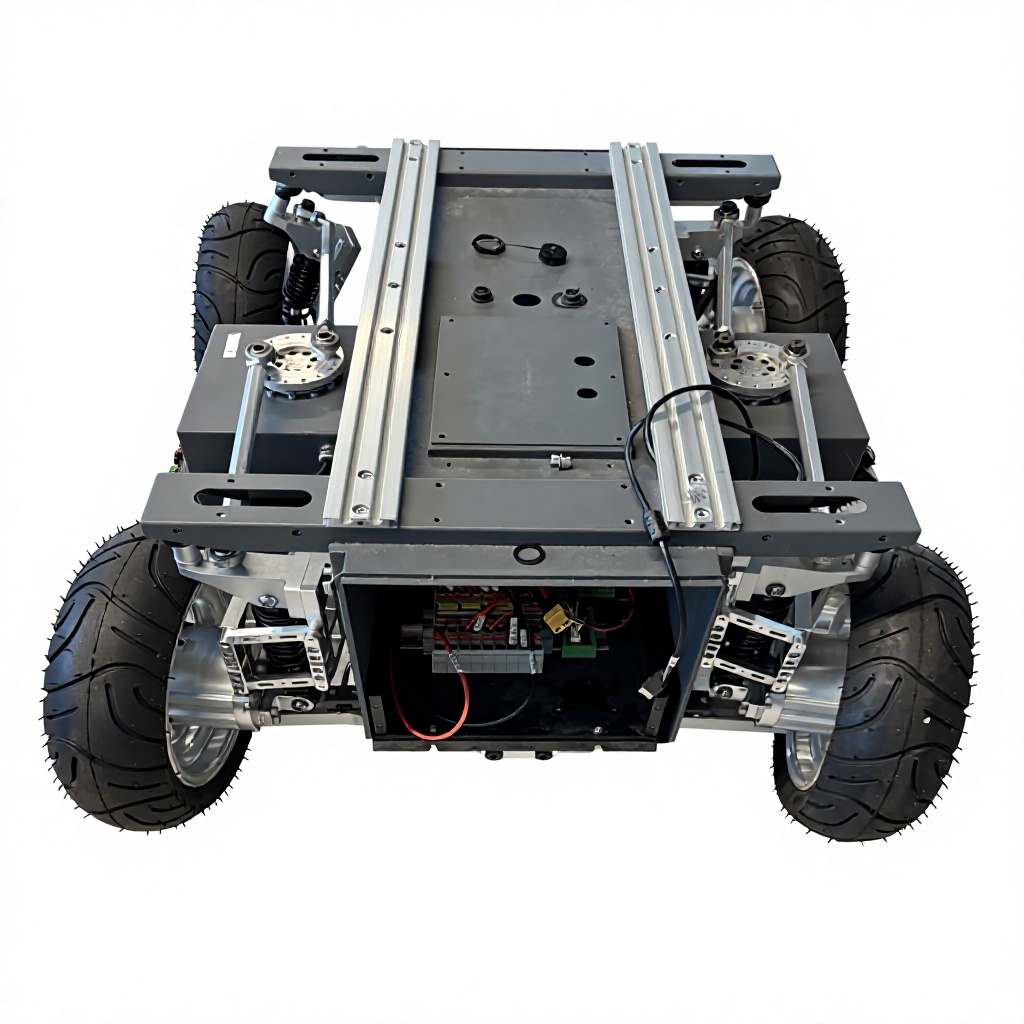
Wheeled Robot Chassis
Configurable 4WD, four-wheel-steering, and omnidirectional bases for autonomous mobile robots.
- 4WD / 4WS
- Omnidirectional
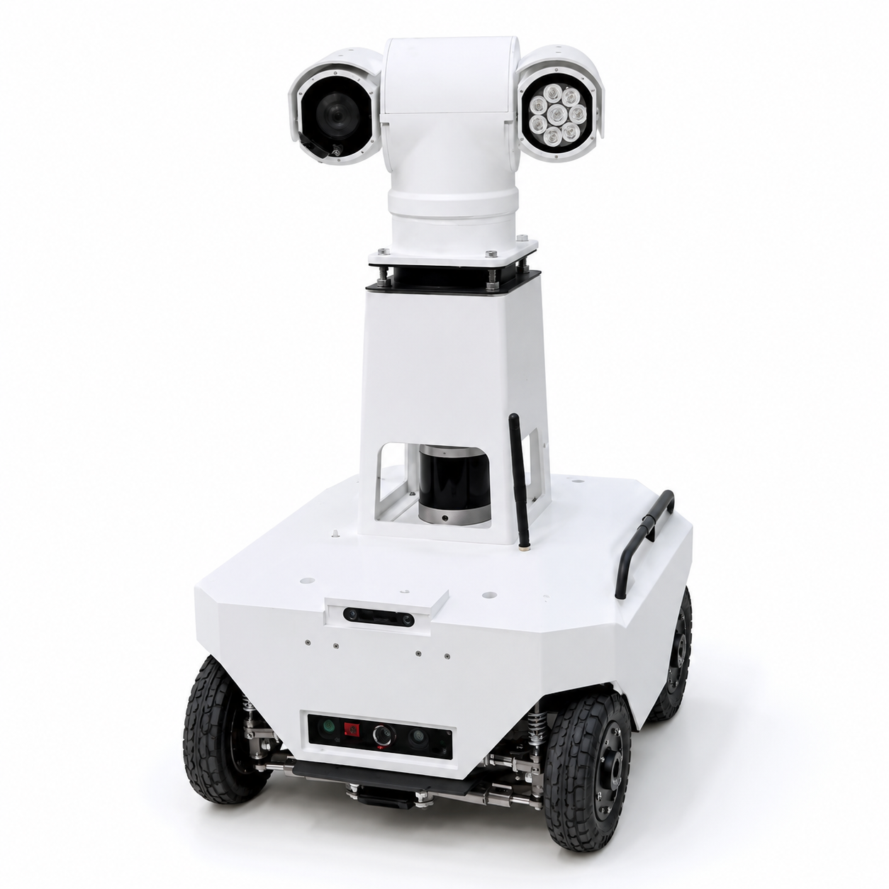
Inspection & Special Robots
Autonomous inspection, tracked, and special-purpose robot platforms for field operations and mission payloads.
- Autonomous inspection
- Special purpose
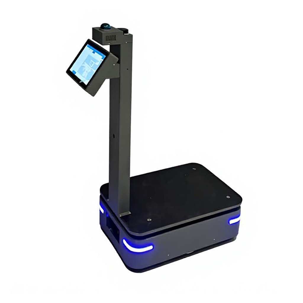
AMR & Delivery Robots
Mobile robot foundations and integrated configurations for material movement and service delivery.
- Logistics
- Service robotics
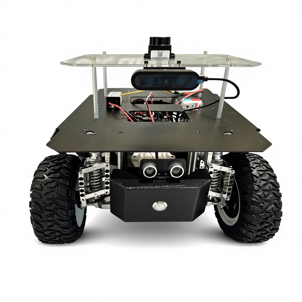
Education & Research Robots
Open development platforms for robotics education, competitions, navigation, and algorithm research.
- Open SDK
- ROS development
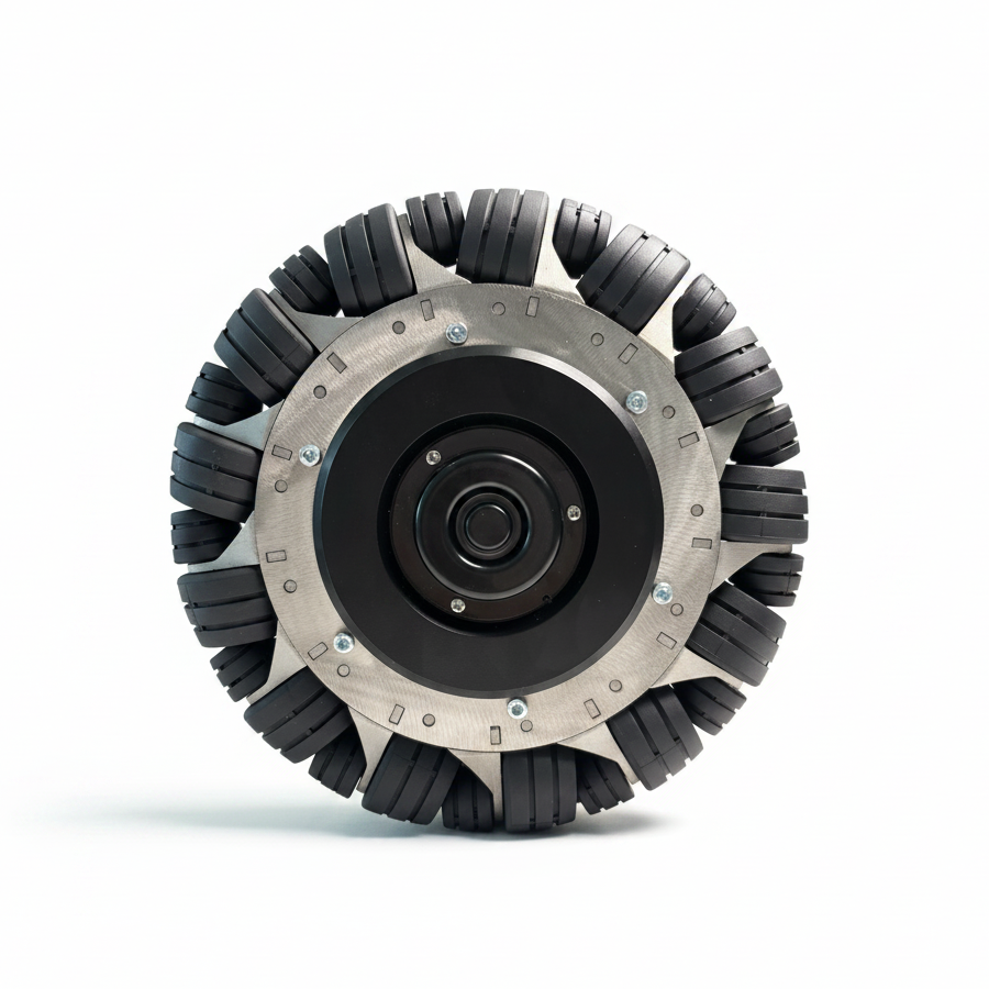
Hub Servo Motors
Integrated wheel-hub drive options for AGV, AMR, service robot, and mobile chassis programs.
- Brushless drive
- Encoder feedback
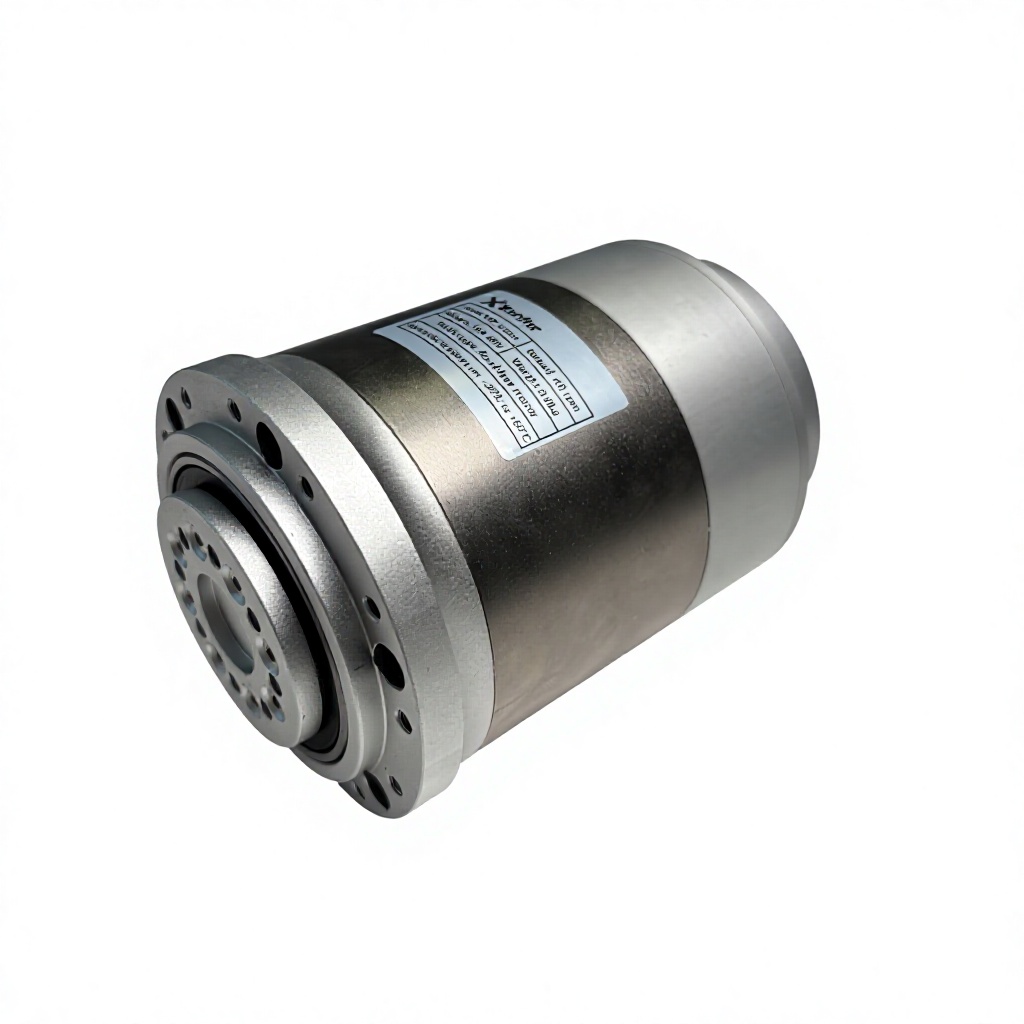
Robot Joint Actuators
Integrated servo joint modules for robotic arms, humanoid robots, exoskeletons, and automation equipment.
- Integrated servo
- Robotic joints
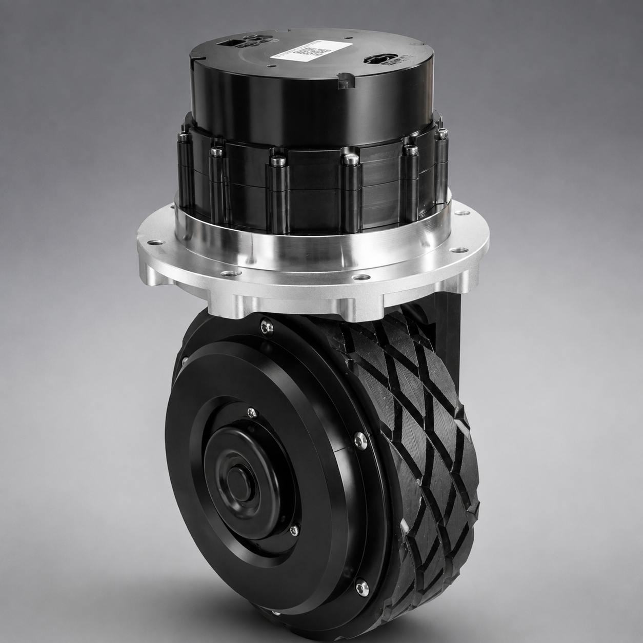
Steering-Drive Modules
Compact steering, drive, reduction, and control assemblies for AGV and AMR mobility systems.
- CAN bus
- Integrated module

Robot Motor Drivers
Brushless servo amplifiers and controllers for robot hub motors and mobile drive systems.
- 24 V / 48 V
- RS485
03 / Mobility technology
Engineering the path between command and motion.
A requirements-led view of drive, steering, terrain contact, controls, and secondary development.
- 01SFLZ SERIES
Four-Wheel-Steering Platforms
The SFLZ chassis family combines four-wheel drive, four-wheel steering, and configurable payload capacity for mobile robot development.
Select the chassis size, battery, payload, and control configuration around the operating route. - 02SFOW500
Omnidirectional Motion
SFOW500 uses an omnidirectional wheel arrangement for lateral, diagonal, and in-place movement in constrained spaces.
A practical mobility base for AMR, service robot, and autonomous navigation projects. - 04SFSD10B-P
Integrated Steering Drive
SFSD10B-P combines drive, steering, reduction, and feedback functions in a compact wheel module.
Integrate a steerable wheel module into AGV and AMR chassis designs through the published electrical and mechanical configuration. - 05SFWH SERIES
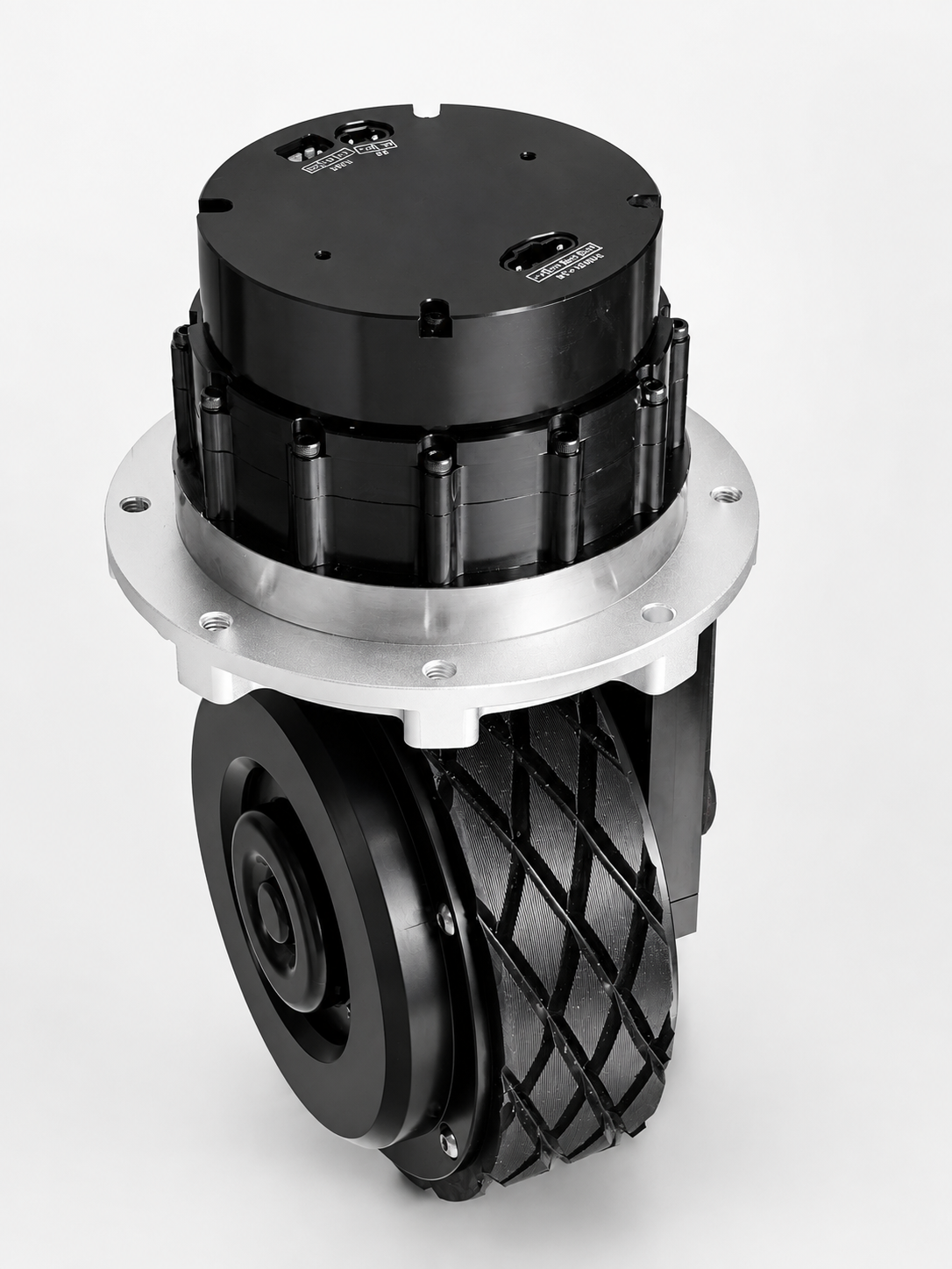
Hub Servo Motor Integration
The SFWH motor family combines the wheel, brushless drive, and encoder feedback in an integrated assembly.
Choose wheel diameter, voltage, power, torque, and load capability for the mobile platform. - 06SFJR SERIES
Robot Joint Actuation
SFJR joint actuators package motor, reduction, sensing, and servo control for articulated robot mechanisms.
Match rated torque, peak torque, voltage, speed, and mechanical interface to the target joint. - 07SFMD SERIES
Motor Control
SFMD drivers provide brushless motor control options for robot hub motors and mobile drive systems.
Confirm operating voltage, peak and continuous current, communication interface, feedback, and motor matching.
04 / Featured products
Representative platforms and motion components.
Compare representative configurations, then discuss the required mechanical, electrical, and control interfaces with our team.
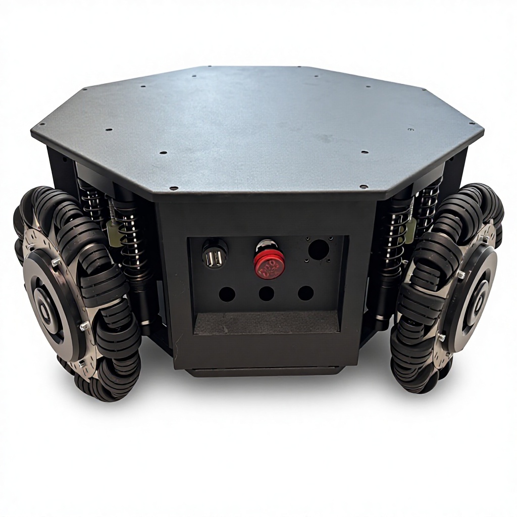
100 kg Omnidirectional Robot Chassis
An omnidirectional mobile base with four-wheel independent suspension for payload integration, autonomous navigation, and service-robot development.
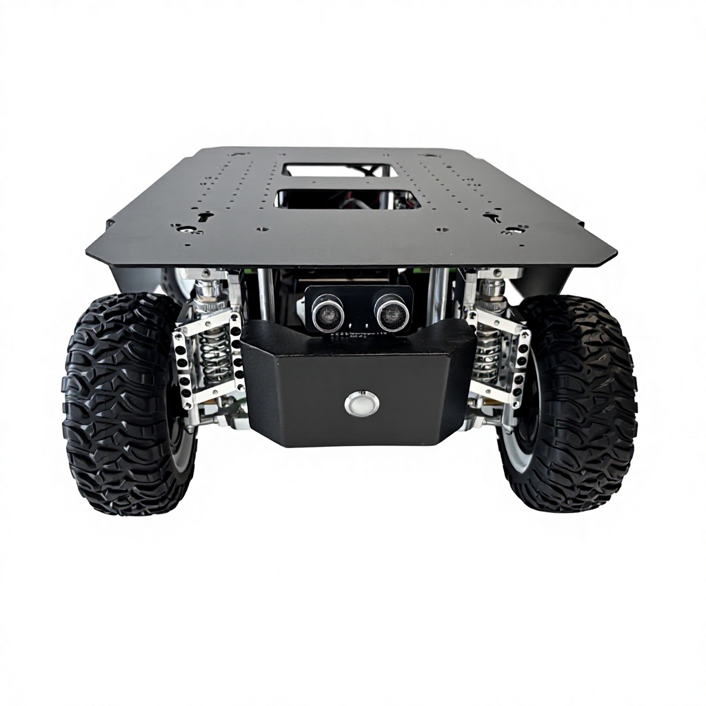
Education & Research Robot Platform
An open four-wheel platform prepared for robotics education, ROS development, navigation experiments, competitions, and AI coding projects.
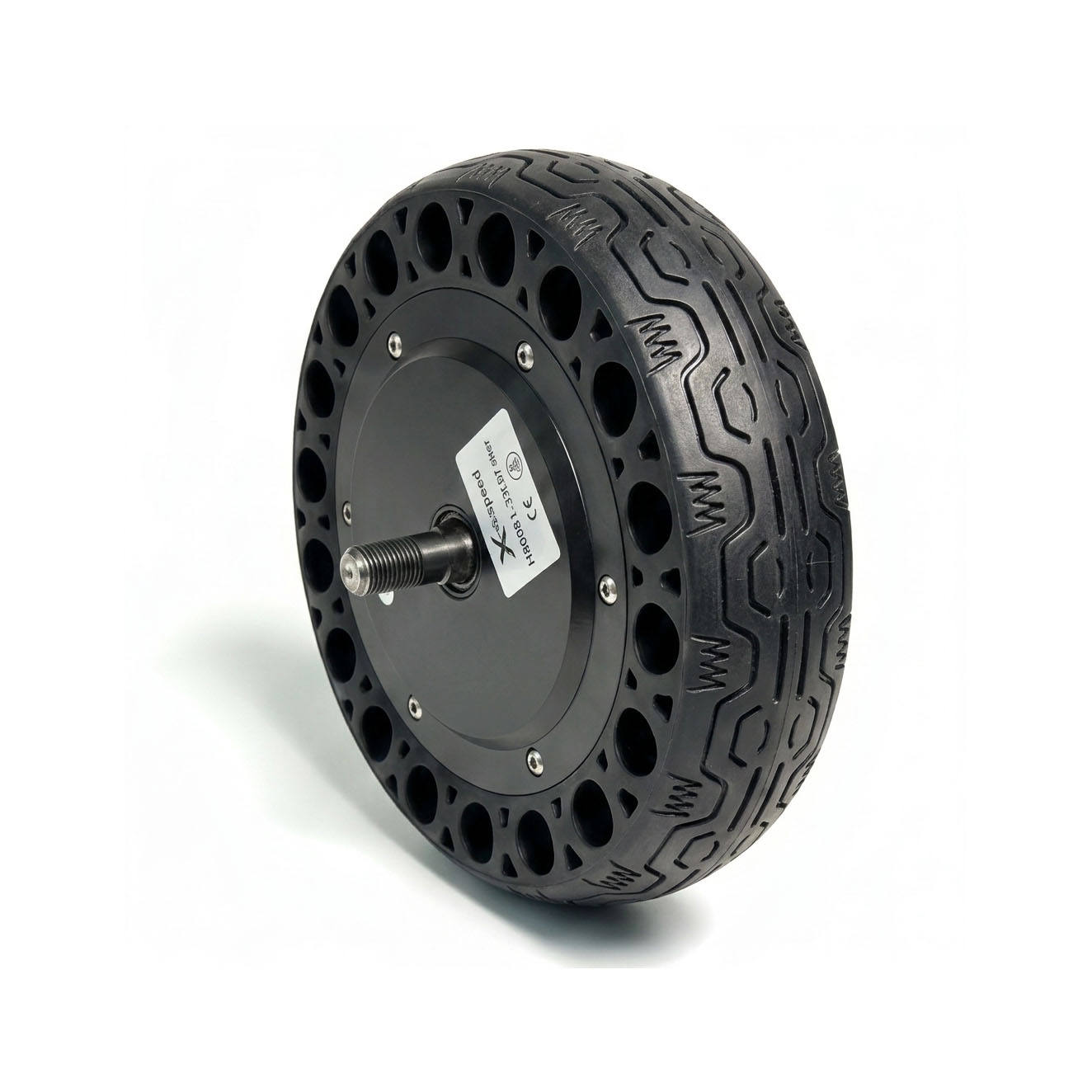
8-Inch Hub Servo Motor
A compact brushless wheel-hub servo motor for AGV, AMR, service robot, and mobile chassis drive applications.
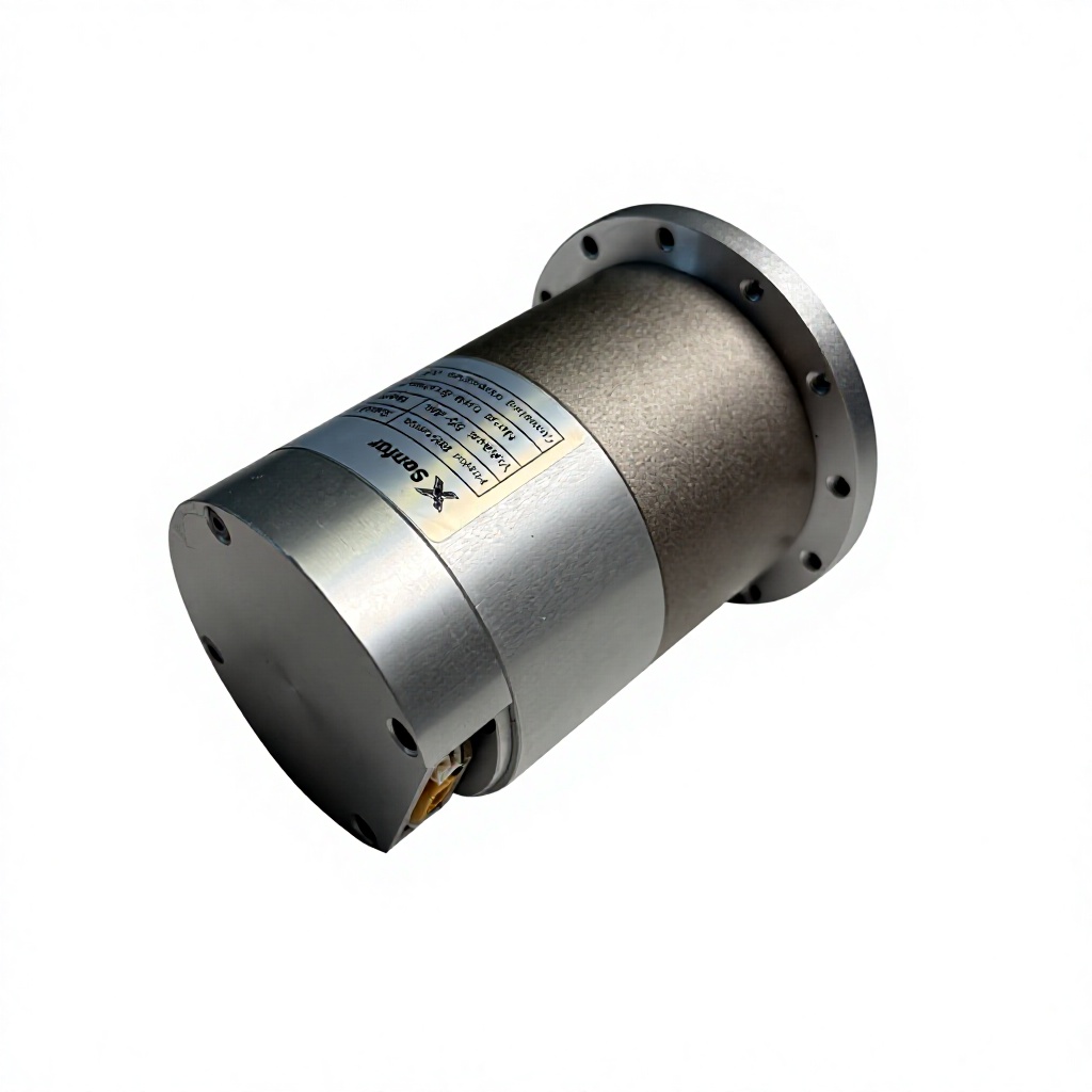
Integrated Robot Joint Actuator
An integrated smart servo joint for robotic arms, automation equipment, humanoid development, and other articulated robot systems.
05 / Applications
Mobility platforms for real engineering contexts.
Start with the environment, route, payload, integration, and control requirements of the program.
Research & Education
Teams need an extensible mobile base for teaching, prototyping, and algorithm development.
Explore application ↗Autonomous Navigation
Autonomy teams need chassis behavior that can be modeled and integrated into the navigation stack.
Explore application ↗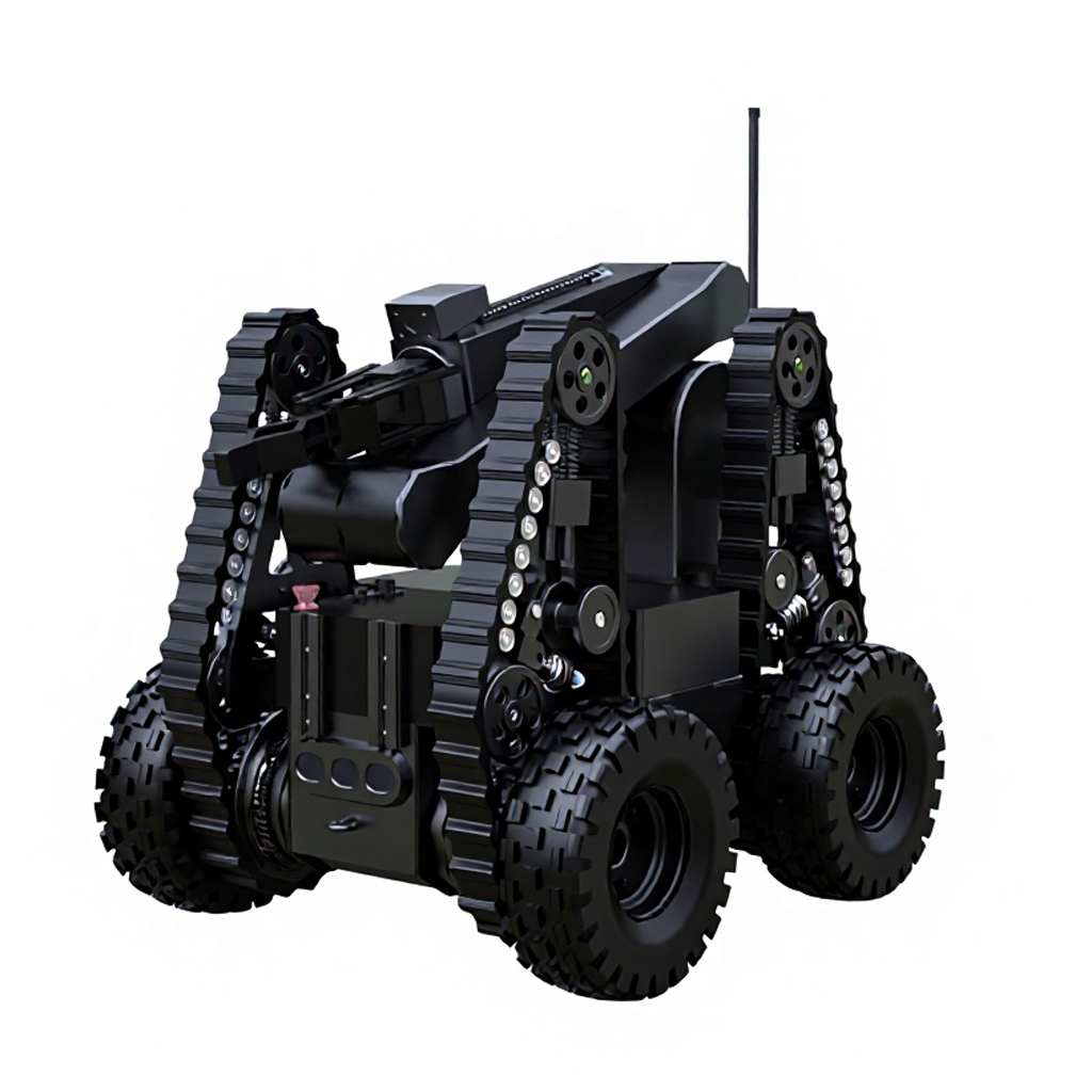
Outdoor Inspection
Inspection programs face uneven surfaces, constrained access, and application-specific payloads.
Explore application ↗Logistics & Material Handling
Material movement requires a chassis architecture that fits the route and system integration plan.
Explore application ↗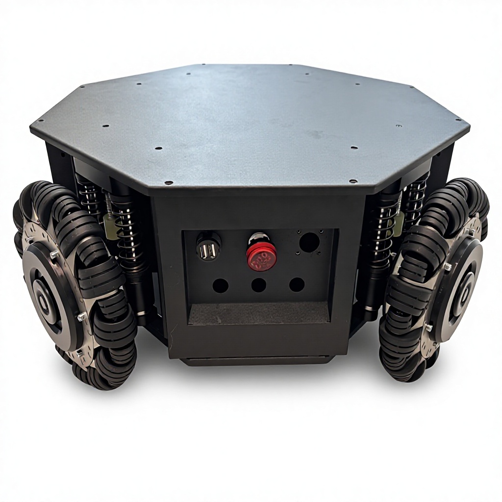
Special-Purpose Robotics
Specialized programs rarely fit a generic chassis without mechanical and control trade-offs.
Explore application ↗06 / Integration workflow
Move from product selection to an integration-ready configuration.
Share the platform, motion, payload, interface, and operating requirements so the product configuration can be reviewed as a complete system.
Define the requirements
Payload, dimensions, terrain, control interface, and project timeline.
Select the configuration
Match the platform, motor, actuator, steering, and controller options to the application.
Confirm the handoff
Align drawings, interfaces, technical documents, and delivery boundaries before implementation.
Start a project conversation
Build Your Next Mobile Robot Platform with Senfar
Tell us your payload, dimensions, terrain, control interface, and customization requirements.